Omega-Type Metamaterial Meta-Lens for 8–12 GHz: Theory, Design & Parameter Retrieval

This project demonstrates the design and analysis of a prism-like meta-lens composed of omega-type metamaterial unit cells operating in the 8–12 GHz band. Each unit cell provides electric and magnetic resonances that can be tuned to realize a negative–zero–positive (NZP) effective refractive index profile. By arranging these cells with appropriate gradients, the bulk structure behaves as a refractive lens, bending and focusing incident microwave beams. The post explains the underlying metamaterial theory, equivalent circuit interpretation, and effective-medium models for the omega inclusion, followed by a practical design workflow and CST-based characterization. An interactive calculator is provided to estimate magnetic and electric plasma frequencies, retrieve effective permittivity and permeability from S-parameters, and check the balanced condition required for overlapping negative ε and μ. Readers can request CST models and support via email for deeper exploration and reproduction of the results.
Keywords: Omega-Type Metamaterial, Meta-Lens, Negative Refractive Index, Plasma Frequency, Effective Permittivity, Effective Permeability, X-Band
1. Introduction
Metamaterials are artificially engineered media whose effective permittivity \( \epsilon_{\text{eff}} \) and permeability \( \mu_{\text{eff}} \) can be tailored to values not available in naturally occurring materials, including negative-index, near-zero-index (NZI), and strongly dispersive regimes. Among the various unit cells proposed for microwave frequencies, omega-type inclusions provide both electric and magnetic responses using a compact, asymmetric loop-and-arm geometry. By carefully designing the resonant frequencies and plasma frequencies of these inclusions, one can create bulk media where the refractive index \( n_{\text{eff}} = \sqrt{\epsilon_{\text{eff}}\mu_{\text{eff}}} \) transitions from negative to zero to positive across the operating band, enabling collimation, beam steering, and lensing.
In this RFInside project, we focus on an 8–12 GHz meta-lens built from a periodic arrangement of omega-type unit cells. The goal is to provide a teaching-oriented yet technically detailed guide that bridges the gap between the original research paper and a practical CST implementation that students can adapt for their own meta-lens designs.

2. Omega-Type Unit Cell and Effective Medium Theory
2.1 Geometry and Equivalent Circuit
The omega-type unit cell consists of a conductive loop with an “Ω”-like shape, typically realized as a printed metallic pattern on a dielectric substrate. Short arms extend from the loop and connect asymmetrically to the host medium, introducing magnetoelectric coupling. The essential parameters are:
- Loop dimensions (length and width) determining inductance \( L \)
- Gap spacing and arm separation forming capacitance \( C \)
- Metal thickness and trace width affecting series resistance \( R \)
- Substrate permittivity \( \epsilon_r \) and thickness controlling coupling to free space
At microwave frequencies, each omega inclusion can be approximated by a series RLC circuit with resonance angular frequency
\( \omega_0 = \frac{1}{\sqrt{LC}} \),
and damping factors determined by conductor and dielectric losses. The macroscopic material parameters emerge from the collective response of many such inclusions embedded in the host medium with filling factor \( F \) (ratio of inclusion volume to unit-cell volume).
2.2 Dispersive Permittivity and Permeability
For a periodic arrangement of omega-type inclusions, the frequency dependence of the effective parameters can be written in a Lorentz–Drude form:
\( \epsilon_{\text{eff}}(\omega) \approx \epsilon_{\infty} - \frac{\omega_{pe}^2}{\omega^2 + j\gamma_e \omega} \),
\( \mu_{\text{eff}}(\omega) \approx 1 - \frac{F \, \omega^2}{\omega^2 - \omega_0^2 + j\gamma_m \omega}, \)
where \( \epsilon_{\infty} \) is the high-frequency permittivity, \( \omega_{pe} \) is the electric plasma frequency, and \( \omega_0 \) is the resonant angular frequency associated with the magnetic loop. The factor \( \gamma_e \) and \( \gamma_m \) represent loss terms. Neglecting losses for first-order design, the expressions simplify to:
\( \epsilon_{\text{eff}}(\omega) \approx \epsilon_{\infty} - \frac{\omega_{pe}^2}{\omega^2}, \quad \mu_{\text{eff}}(\omega) \approx 1 - \frac{F \, \omega^2}{\omega^2 - \omega_0^2}. \)
The magnetic plasma frequency \( \omega_{pm} \) is defined as the frequency where \( \mu_{\text{eff}}(\omega_{pm}) = 0 \). Solving
\( 1 - \frac{F \omega_{pm}^2}{\omega_{pm}^2 - \omega_0^2} = 0 \)
yields
\( \omega_{pm} = \frac{\omega_0}{\sqrt{1 - F}}. \)
For the electric response, the electric plasma frequency is directly
\( \omega_{pe} \approx \omega_{z\epsilon}, \)
where \( \omega_{z\epsilon} \) is the frequency at which \( \Re\{\epsilon_{\text{eff}}\} \) crosses zero.
2.3 Negative–Zero–Positive Index Operation
The effective refractive index is
\( n_{\text{eff}}(\omega) = \pm \sqrt{\epsilon_{\text{eff}}(\omega)\mu_{\text{eff}}(\omega)}. \)
A negative-index band occurs where \( \Re\{\epsilon_{\text{eff}}\} < 0 \) and \( \Re\{\mu_{\text{eff}}\} < 0 \). If the electric and magnetic plasma frequencies are tuned such that \( \omega_{pe} \approx \omega_{pm} \), the overlapping region of negative ε and μ becomes broader and well-centered in the operating band. Around this region, one can also identify a near-zero-index frequency (NZI point) where \( \Re\{n_{\text{eff}}\} \approx 0 \), giving rise to collimation and beam steering effects.
3. Meta-Lens Architecture for 8–12 GHz
3.1 Operating Band and Material Choices
The meta-lens in this project is designed for the X-band (8–12 GHz). The unit cell size is chosen to remain deeply subwavelength (typically < λ0/8), ensuring that the homogenization assumptions hold. A low-loss microwave substrate (or 3D printed dielectric) with relative permittivity between 2 and 4 is used as the host, while the omega-shaped metallization is etched on thin copper or plated on the dielectric surface.
3.2 Gradual Index Profiling
By slightly varying the geometry of the omega inclusions (e.g., loop length, gap, arm length) along a single direction, it is possible to engineer a graded profile of effective refractive index. When the slab is cut into a prism-like shape, incident plane waves undergo spatially varying phase delays, bending toward the region of higher index, similar to a conventional lens.
3.3 CST Implementation Outline
In CST Microwave Studio, the meta-lens is typically modeled as a finite array of omega-type unit cells:
- Define the unit cell geometry (loop, gap, arms) and substrate.
- Create a 2D periodic array in the x–y plane for one or more periods.
- Apply periodic boundary conditions or model a finite prism structure with open (add space) boundaries.
- Excite the structure with a plane wave or waveguide port and compute \( S_{11} \) and \( S_{21} \) over 8–12 GHz.
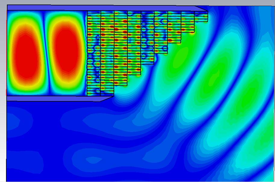
- Visualize electric field distribution and Poynting vector to confirm focusing behavior.
4. Omega-Type Metamaterial Calculators
The following calculators provide a simplified way to connect physical design parameters and measured or simulated S-parameters to effective material properties:
- Calculator A: Magnetic plasma frequency from resonant frequency and filling factor.
- Calculator B: Effective index, permittivity, and permeability from S-parameter magnitude and phase.
- Calculator C: Balanced condition check between electric and magnetic plasma frequencies for negative–zero–positive index operation.
4.1 Calculator A – Magnetic Plasma Frequency
For an omega-type resonant inclusion with resonance frequency \( f_0 \) and filling factor \( F \), the lossless effective permeability can be approximated as:
\( \mu_{\text{eff}}(\omega) \approx 1 - \frac{F \omega^2}{\omega^2 - \omega_0^2}. \)
The magnetic plasma frequency \( f_{pm} \) is where \( \mu_{\text{eff}} = 0 \), giving:
\( f_{pm} = \frac{f_0}{\sqrt{1 - F}}. \)
Note: This expression neglects loss and higher-order effects but is useful for initial tuning of negative-μ bands in the 8–12 GHz range.
4.2 Calculator B – Effective ε and μ from S-Parameters
Given the S-parameters of a metamaterial slab of thickness \( d \), a simplified retrieval can estimate the effective refractive index and impedance, and thus \( \epsilon_{\text{eff}} \) and \( \mu_{\text{eff}} \). For normal incidence:
\( n_{\text{eff}} \approx -\frac{\phi_{21}}{k_0 d}, \quad k_0 = \frac{2\pi f}{c}. \)
An NRW-like formula for the effective impedance (using magnitudes only) is:
\( z_{\text{eff}} \approx \sqrt{ \frac{(1 + |S_{11}|)^2 - |S_{21}|^2} {(1 - |S_{11}|)^2 - |S_{21}|^2} }. \)
Finally,
\( \epsilon_{\text{eff}} \approx \frac{n_{\text{eff}}}{z_{\text{eff}}}, \quad \mu_{\text{eff}} \approx n_{\text{eff}} z_{\text{eff}}. \)
Note: This is a single-frequency approximation and does not handle phase-branch ambiguity. For rigorous retrieval, use a sweep of S-parameters and a full NRW implementation.
4.3 Calculator C – Balanced Electric and Magnetic Plasma Frequencies
For broadband negative-index or negative–zero–positive (NZP) behavior, the electric and magnetic plasma frequencies should be close to each other:
\( \omega_{pe} \approx \omega_{pm}. \)
This calculator checks how well-balanced the plasma frequencies are around a chosen center frequency \( f_c \) in the 8–12 GHz band.
Rule of thumb: if \( |f_{pe} - f_{pm}| / f_c \lesssim 0.1 \), the material is reasonably balanced for NZP operation; otherwise, it is electric- or magnetic-dominant.
5. Field Distribution and Meta-Lens Behavior
For frequencies near the negative-index region, the omega-type cells support strong localized magnetic fields around the loop and enhanced electric fields in the gaps. When many cells are combined into a prism-shaped slab, the phase accumulation across the thickness leads to refraction at angles not predicted by conventional Snell’s law with positive index. Around the near-zero-index point, the slab behaves as a directive radiator, collimating incident waves with minimal phase variation across its aperture.
6. Practical Design Considerations
- Losses: High metal and dielectric losses reduce the depth of the negative-index band and flatten dispersion. Choose low-loss substrates and maintain good metal conductivity.
- Fabrication tolerances: Small errors in gap size or arm length can shift \( f_0 \), altering both \( f_{pm} \) and the NZP behavior. Always simulate worst-case tolerances.
- Coupling between layers: In multi-layer meta-lenses, inter-layer coupling may introduce additional resonances; full 3D simulations are recommended.
- Bandwidth: Negative-index regions are usually narrow; design the lens for a specific application bandwidth (e.g., 10–11 GHz) rather than trying to cover the entire 8–12 GHz range.
- Polarization: Omega-type inclusions are often polarization-sensitive; ensure the incident polarization aligns with the intended excitation of the loop and arms.
7. Python Calculator Download
A standalone Python script implementing all three calculators (magnetic plasma frequency, effective parameter retrieval from S-parameters, and NZP balance check) is provided for offline use.
Download Omega Meta-Lens Calculator (Python)8. Support & Simulation Files
The full CST model of the omega-type unit cell and meta-lens, along with detailed simulation settings and parameter sweeps, are available on request for academic and self-learning purposes.
For technical support or to request the CST simulation files, please email: director@rfinside.com
9. References
- Primary omega-type metamaterial meta-lens paper (provide full IEEE citation here as per your source).
- Pendry, J. B. et al., “Magnetism from conductors and enhanced nonlinear phenomena,” IEEE Transactions on Microwave Theory and Techniques, 1999.
- Smith, D. R. et al., “Composite medium with simultaneously negative permeability and permittivity,” Physical Review Letters, 2000.
- Caloz, C., Itoh, T., Electromagnetic Metamaterials: Transmission Line Theory and Microwave Applications, Wiley, 2005.
- Chen, X. et al., “Robust method to retrieve the constitutive effective parameters of metamaterials,” Physical Review E, 2004.