Antenna Factor Calculation
Antenna factor is one of the most important bridge quantities between what an antenna receives and what an EMI / EMC measurement receiver reports. It connects electric field strength in free space to terminal voltage at the antenna output, making it central to radiated emission testing, calibration practice, site validation, and field-strength estimation.
1) What is antenna factor?
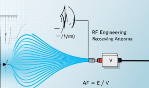
Antenna factor, usually abbreviated as AF, tells us how to convert the measured voltage at the antenna terminals into incident electric field strength. In the simplest form:
Here, E is the incident electric field strength and V is the received terminal voltage. So antenna factor acts as a calibration bridge between a radiated field and an electrical output quantity.
Why RF engineers care about AF
- Radiated EMC/EMI testing needs field strength, not just receiver voltage.
- Calibration laboratories specify antenna factor versus frequency.
- AF helps compare receiving antennas such as dipoles, biconicals, log-periodics, and horns.
- It connects theory, measurement, and compliance reporting.
2) Historical and measurement background
Antenna factor became especially important when radio engineering moved from communication problems toward standardized electromagnetic compatibility measurement. In practical testing, the engineer wants to know: what electric field exists in space around a device under test? But the receiver does not read field directly; it reads voltage. That is why the receiving antenna must be treated as a calibrated transducer.
Over time, AF curves became standard deliverables for measurement antennas such as dipoles, biconicals, log-periodics, and horns. In that sense, antenna factor is both a theoretical quantity and a metrological quantity.
From theory to compliance
Textbook derivations explain why AF behaves the way it does. Calibration data tell you the actual values used in real EMC measurements across frequency.
3) Core definitions and units
In linear form:
If E is in V/m and V is in V, then AF has units:
In practical EMC work, AF is often expressed in logarithmic form:
Then the field strength equation becomes:
| Quantity | Symbol | Units | Meaning |
|---|---|---|---|
| Electric field strength | E | V/m or dBµV/m | Incident field in space |
| Terminal voltage | V | V or dBµV | Voltage delivered by the receiving antenna |
| Antenna factor | AF | 1/m or dB/m | Conversion factor from voltage to field strength |
4) Main equations and derivation
A physically intuitive route to antenna factor uses effective length. If the receiving antenna has effective length he, then under matched conditions:
Rearranging gives:
So AF is simply the reciprocal of effective length. A larger effective length means higher received voltage for the same field, which means a lower antenna factor.
Gain-based route
For a receiving antenna:
The incident power density of a plane wave is:
with free-space impedance:
Received available power is:
Under matched conditions, if the receiving system resistance is R:
Therefore:
5) Antenna factor in dB form
Starting with:
Taking 20 log10 of both sides gives:
If cable loss and amplifier gain must be included, the practical lab equation becomes:
Why engineers prefer the dB form
- Multiplication becomes addition.
- It aligns directly with receiver readout in dBµV.
- It makes correction terms easy to include.
6) Relation with effective length, gain, and frequency
Antenna factor is strongly frequency-dependent. Since:
substituting into the gain-based formula gives:
This shows that if gain remained constant, AF would generally rise with frequency. In practice, the actual AF curve depends on both frequency and antenna structure.
7) Antenna Factor Calculator
The calculator below supports two routes:
- Mode A: calculate AF from electric field and measured voltage
- Mode B: calculate AF from frequency and gain in a matched receiving system
Interactive Antenna Factor Calculator
Choose a mode, enter the values, and the calculator will show both linear and dB results with step-by-step working.
- Select a mode and click Calculate.
8) Worked examples
Example 1: AF from field-to-voltage ratio
Suppose the incident electric field is 0.5 V/m and the received terminal voltage is 10 mV.
Example 2: AF from gain at 300 MHz
Assume frequency = 300 MHz, gain = 2.15 dBi, and reference resistance = 50 Ω.
9) Engineering interpretation tips
How to read an AF curve
- AF is frequency-dependent.
- Broadband measurement antennas trade gain flatness, bandwidth, and pattern behavior.
- A lower AF usually indicates higher voltage sensitivity for a given field.
Where learners get confused
- AF is related to gain but is not the same thing.
- AF is not dimensionless; in linear form its unit is 1/m.
- dB formulas must use consistent voltage and field reference units.
10) Common mistakes and further reading
- Using power values in place of terminal voltage without proper conversion.
- Ignoring that the gain-based AF formula assumes matched free-space conditions.
- Ignoring cable losses, preamp gain, or polarization mismatch in practical measurement chains.
- Using theoretical AF even when calibrated AF data are available for the actual antenna.