Split Ring Resonator (SRR) Metamaterial Element for X-Band Applications

This project presents the design and electromagnetic characterization of a split ring resonator (SRR) metamaterial element operating in the X-band. The SRR is implemented as a concentric dual-ring structure with narrow gaps, forming a subwavelength resonant inclusion that can exhibit negative effective permeability and, in combination with complementary structures, negative permittivity. Using a CST Microwave Studio model, the reflection and transmission coefficients (\( S_{11} \) and \( S_{21} \)) of an SRR-loaded slab are obtained, and an approximate retrieval technique is applied to extract the effective refractive index, permittivity \( \epsilon_{\text{eff}} \), and permeability \( \mu_{\text{eff}} \) over frequency. An interactive calculator is provided to estimate \( \epsilon_{\text{eff}} \) and \( \mu_{\text{eff}} \) from measured or simulated S-parameters, enabling students to link full-wave data with homogenized metamaterial parameters.
Keywords: Split Ring Resonator, Metamaterials, Negative Permeability, X-Band, S-parameter Retrieval, Effective Medium
1. Introduction
Artificially engineered metamaterials have enabled exotic electromagnetic responses such as negative refractive index, near-zero index, and highly dispersive effective parameters. Among the earliest and most influential unit cells is the split ring resonator (SRR), introduced as a compact resonant inclusion capable of supporting strong magnetic response at microwave frequencies. By periodically loading a host medium with SRRs, one can realize effective negative permeability around the resonance while maintaining sub-wavelength lattice dimensions.
In this project, we consider a planar SRR element intended for X-band applications (approximately 8–12 GHz). The focus is on:
- Understanding the LC-type resonance mechanism of SRRs;
- Designing the geometry to place the fundamental resonance in the desired band;
- Extracting effective parameters (\( \epsilon_{\text{eff}} \), \( \mu_{\text{eff}} \)) from S-parameters using a simplified retrieval approach.
2. Split Ring Resonator Geometry and Physical Insight
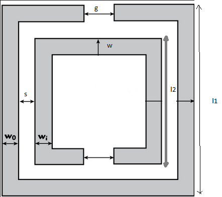
2.1 Geometrical Parameters
A typical planar SRR consists of two concentric metallic rings with narrow splits placed on a dielectric substrate backed by a ground plane or suspended in free space. The main geometrical parameters are:
- \( l_1 \): outer ring side length;
- \( l_2 \): inner ring side length;
- \( w \): conductor (ring) width;
- \( s \): spacing between the inner and outer rings;
- \( g \): gap width in each ring;
- \( w_0, w_i \): feed line or waveguide widths in some implementations;
- \( h \): substrate thickness, with relative permittivity \( \epsilon_r \).
2.2 LC Resonance and Effective Permeability
When the SRR is excited by a time-varying magnetic field normal to the plane of the rings, circulating currents are induced, leading to a resonant response. The structure behaves roughly like a series LC circuit, where:
- Inductance \( L \) is associated with the current loop along the metallic rings;
- Capacitance \( C \) arises from the gaps and inter-ring spacing.
The approximate resonant frequency of the SRR can be written as:
\( f_0 \approx \frac{1}{2\pi \sqrt{LC}} \)
Around this frequency, the effective permeability of an SRR-loaded medium can become negative, enabling left-handed or double-negative (DNG) behavior when combined with structures providing negative permittivity.
3. SRR Design for X-Band Operation
3.1 Substrate and Frequency Specification
For an X-band design, the target resonance might be chosen near 9–10 GHz, taking into account fabrication tolerances and coupling effects in an array. Typical design steps:
- Select substrate material with permittivity \( \epsilon_r \) and thickness \( h \) (e.g., Rogers, FR-4).
- Choose outer ring size \( l_1 \) based on the approximate effective wavelength at the target frequency (usually \( l_1 \ll \lambda_0 \) to maintain subwavelength size).
- Set inner ring size \( l_2 \), spacing \( s \), and gap \( g \) to tune capacitance and coupling.
- Adjust ring width \( w \) to control inductance and loss.
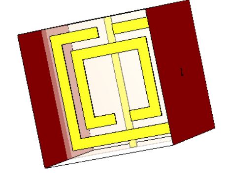
3.2 Simulation Setup in CST
In CST Microwave Studio, the SRR can be simulated in a unit-cell configuration with periodic boundary conditions (PBCs) or as a finite slab excited by a waveguide/plane wave. For parameter retrieval, a common approach is to model a finite-thickness slab of repeated SRR cells and compute S-parameters for normal incidence.
- Define unit cell dimensions and apply periodic boundaries in the lateral directions.
- Use open (add space) or Floquet boundaries along the propagation direction.
- Excite the structure with a waveport or plane wave; extract \( S_{11}(f) \) and \( S_{21}(f) \).
- Export magnitude (in dB) and phase (in degrees) for the retrieval process.
4. Effective Medium Approximation and Parameter Retrieval
When the SRR lattice period is much smaller than the free-space wavelength, the structure can be treated as an effectively homogeneous slab characterized by an equivalent permittivity \( \epsilon_{\text{eff}} \) and permeability \( \mu_{\text{eff}} \). From measured or simulated S-parameters, several retrieval techniques exist, such as the Nicholson–Ross–Weir (NRW) method and its variants.
4.1 Basic Relations
For a slab of thickness \( d \), the complex transmission coefficient can be approximated as:
\( S_{21} \approx |S_{21}| e^{j\phi_{21}} \approx e^{-j k_0 n_{\text{eff}} d} \),
where \( k_0 = \frac{2\pi f}{c} \) is the free-space wavenumber and \( n_{\text{eff}} \) is the effective refractive index. Ignoring multiple reflections for an approximate retrieval, the real part of \( n_{\text{eff}} \) can be estimated from the phase of \( S_{21} \):
\( n_{\text{eff}} \approx -\frac{\phi_{21}}{k_0 d} \),
with \( \phi_{21} \) expressed in radians. The effective wave impedance \( z_{\text{eff}} \) can be approximated from the magnitudes of \( S_{11} \) and \( S_{21} \) under moderate-loss assumptions:
\( z_{\text{eff}} \approx \sqrt{\frac{(1 + |S_{11}|)^2 - |S_{21}|^2}{(1 - |S_{11}|)^2 - |S_{21}|^2}}. \)
Once \( n_{\text{eff}} \) and \( z_{\text{eff}} \) are known, the effective permittivity and permeability follow:
\( \epsilon_{\text{eff}} \approx \frac{n_{\text{eff}}}{z_{\text{eff}}}, \quad \mu_{\text{eff}} \approx n_{\text{eff}} z_{\text{eff}}. \)
The interactive calculator below implements this approximate retrieval using frequency, slab thickness, and S-parameter data (magnitude and phase). It is intended for quick educational analysis; for rigorous designs, full complex NRW retrieval with branch selection should be performed in a dedicated Python or MATLAB script.
5. Interactive SRR Metamaterial Parameter Calculator
Enter the operating frequency, slab thickness, and S-parameters (from CST or measurements). Magnitudes are specified in dB, and the phase of \( S_{21} \) is given in degrees. The calculator returns the approximate effective refractive index, permittivity, and permeability.
5.1 Effective ε and μ from S-Parameters
6. Discussion of Simulation Results
When the SRR geometry is tuned properly, the retrieved effective parameters typically show a Lorentz-type dispersion in \( \mu_{\text{eff}} \), with a region where \( \mu_{\text{eff}} < 0 \) just above the resonance frequency. In some designs, \( \epsilon_{\text{eff}} \) remains close to unity, enabling negative-index behavior only when combined with additional capacitive elements or complementary SRRs.
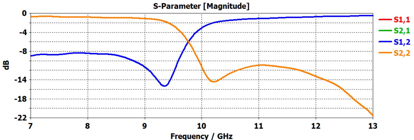
Key observations to highlight in the X-band SRR design:
- Sharp resonance in |S21| corresponding to strong magnetic response.
- Phase jump in \( S_{21} \) around the resonance, reflected in the effective index.
- Frequency band where \( \Re\{\mu_{\text{eff}}\} \) becomes negative, while loss (imaginary part) remains acceptable.
- Sensitivity of resonance to geometric parameters such as gap \( g \), spacing \( s \), and ring width \( w \).
7. Downloadable Project Files (CST + Python)
To reproduce and extend this SRR metamaterial project, a ZIP archive is provided containing:
- CST Microwave Studio model of the X-band SRR unit cell / slab.
- Python script implementing a more detailed parameter retrieval workflow using S-parameter data.
- A concise readme describing geometry parameters, simulation settings, and how to export/import data.
8. References
- Pendry, J. B., Holden, A. J., Robbins, D. J., & Stewart, W. J. (1999). Magnetism from conductors and enhanced nonlinear phenomena. IEEE Transactions on Microwave Theory and Techniques, 47(11), 2075–2084.
- Smith, D. R., Padilla, W. J., Vier, D. C., Nemat-Nasser, S. C., & Schultz, S. (2000). Composite medium with simultaneously negative permeability and permittivity. Physical Review Letters, 84(18), 4184–4187.
- Veselago, V. G. (1968). The electrodynamics of substances with simultaneously negative values of ε and μ. Soviet Physics Uspekhi, 10(4), 509–514.
- Caloz, C., & Itoh, T. (2005). Electromagnetic Metamaterials: Transmission Line Theory and Microwave Applications. Wiley.
- Chen, X., Grzegorczyk, T. M., Wu, B.-I., Pacheco, J., & Kong, J. A. (2004). Robust method to retrieve the constitutive effective parameters of metamaterials. Physical Review E, 70(1), 016608.
- Simovski, C. R. (2007). On electromagnetic characterization and homogenization of metamaterials. Journal of Optics A: Pure and Applied Optics, 9(3), S259–S273.