Dielectric Resonator Antenna (Square DRA Fed by Slot + Microstrip at 5.5 GHz)

This project presents the design, analysis, and characterization of a square dielectric resonator antenna (DRA) operating near 5.5 GHz. The antenna consists of a high-permittivity dielectric block mounted on a ground plane and energized through a slot aperture coupled to a microstrip feed line. DRAs offer excellent efficiency, wide bandwidth, and low loss at microwave frequencies due to the absence of conductor losses associated with metallic patch antennas. The post covers theoretical background, mode analysis, sizing equations, complete CST workflow, and an interactive calculator for estimating DRA dimensions or solving for resonant frequency. A downloadable ZIP includes the CST model and corresponding Python scripts.
Keywords: Dielectric Resonator Antenna, Square DRA, TE111 Mode, Slot Coupling, 5.5 GHz, High-Permittivity Resonators
1. Introduction
Dielectric resonator antennas (DRAs) use a block of high-permittivity dielectric material as the radiating element instead of metal. Compared to microstrip patches, DRAs offer:
- Low loss (no surface current metal losses)
- High radiation efficiency even at millimeter-wave bands
- Wide impedance bandwidth (5–20%)
- Multiple easily-excitable modes (TE111, TM111, higher-order)
Square DRAs are especially popular for WLAN / WiFi / 5.5 GHz applications due to their compact size, simple geometry, and stable resonant modes.
2. Theory of Dielectric Resonator Antennas
A dielectric resonator antenna (DRA) operates by confining electromagnetic fields inside a high-permittivity dielectric block and allowing controlled radiation leakage at resonance. Unlike metallic antennas, which rely on surface currents, DRAs store energy inside the dielectric and radiate through the discontinuity at the dielectric–air interface. This makes DRAs extremely efficient, especially at higher microwave and millimeter-wave frequencies where conductor losses become significant.
2.1 Resonant Condition and Modal Analysis
For a rectangular or square DRA, resonant modes are derived using the dielectric waveguide model. The electromagnetic fields inside the resonator obey the three-dimensional Helmholtz equation:
\( \nabla^2 \psi + k^2 \psi = 0 \),
where \( k = k_0 \sqrt{\epsilon_r} \) is the wavenumber inside the dielectric. Assuming a square resonator with dimensions \( a \times a \times h \), the separation of variables leads to modal solutions of the form:
\( k_x = \frac{m\pi}{a}, \quad k_y = \frac{n\pi}{a}, \quad k_z = \frac{p\pi}{h}, \)
where \( m, n, p \) are integers corresponding to TE or TM field distributions. The resonant frequency becomes:
\( f_{mnp} = \frac{c}{2\pi\sqrt{\epsilon_r}} \sqrt{k_x^2 + k_y^2 + k_z^2 } \)
For the dominant TE111 mode:
\( f_{111} = \frac{c}{2\pi\sqrt{\epsilon_r}} \sqrt{ \left(\frac{\pi}{a}\right)^2 + \left(\frac{\pi}{a}\right)^2 + \left(\frac{\pi}{h}\right)^2 }. \)
This equation highlights:
- The resonant frequency increases as the dielectric constant decreases.
- The resonant frequency increases for smaller \( a \) or \( h \).
- Strong confinement occurs when \( \epsilon_r \) is high (10–30).
2.2 Effective Permittivity and Radiation Mechanism
A DRA behaves like a dielectric cavity partially open to air. The effective permittivity is lower than the bulk dielectric constant due to field fringing:
\( \epsilon_{\text{eff}} \approx \alpha \epsilon_r + (1 - \alpha) \epsilon_0, \)
where \( \alpha \) depends on the aspect ratio \( a/h \) and mode shape. Larger fringing fields (lower height) promote stronger radiation, improving gain. The TE111 mode radiates like a magnetic dipole oriented along the slot axis.
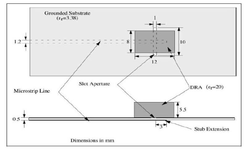
2.3 Slot-Coupled Excitation
The DRA in this project is excited using a narrow slot cut in the ground plane. The microstrip feed beneath the slot generates strong magnetic fields that strongly couple into the TE111 mode. The slot behaves as a magnetic dipole with effective admittance:
\( Y_{\text{slot}} \approx jB_{\text{slot}} = j \cdot \left( \frac{w}{\lambda_0} \right) F(\epsilon_r, h) \)
where \( w \) is the slot width. Proper slot dimensions increase energy transfer into the DRA, improving bandwidth and lowering return loss.
2.4 Quality Factor and Bandwidth
The radiation quality factor is approximately:
\( Q \approx \frac{\omega W_{\text{stored}}}{P_{\text{radiated}}} \)
DRAs with moderate permittivity (εr = 8–12) provide an excellent trade-off between compactness and bandwidth. High-εr DRAs are compact but narrowband.
2.5 Field Distribution
For the TE111 mode:
- Strong E-field at top center and along edges
- Magnetic loop forms around the slot, exciting the mode efficiently
- Broadside radiation from the top surface dominates
3. Design Workflow for a 5.5 GHz Square DRA
- Select dielectric material (e.g., εr = 10–13 for compact designs).
- Choose target mode (TE111 for broadside radiation).
- Initial sizing: Solve for side length \( a \) using the TE111 formula.
- Design slot aperture (length ~ λ0/4, width small for strong coupling).
- Microstrip feed line 50Ω matched to the slot.
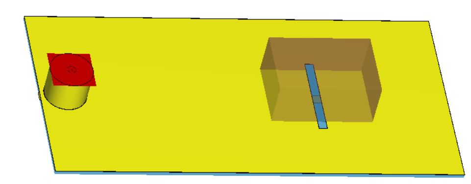
- Optimize in CST for S11, bandwidth, and radiation efficiency.
4. Square DRA Dimension Calculator
Enter dielectric constant and target frequency to estimate the resonator side length \( a \) (for TE111).
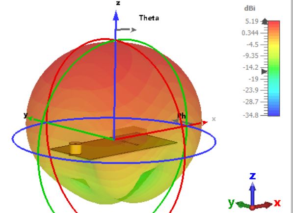
5. Simulation Results and Discussion
A well-designed square DRA at 5.5 GHz typically exhibits:
- Return loss better than –20 dB at resonance
- Bandwidth of 5–10%
- Gain of 5–7 dBi
- Stable broadside radiation pattern
6. Downloadable Project Files (CST + Python)
The ZIP package includes:
- CST model of the square DRA with slot coupling
- Python script for TE111 frequency and dimension estimation
- Readme with simulation guide
7. References
- Long, S. A., McAllister, M. W., & Liang, L. C. (1983). The resonant cylindrical dielectric cavity antenna. IEEE Transactions on Antennas and Propagation, 31(3).
- Petosa, A. (2007). Dielectric Resonator Antenna Handbook. Artech House.
- Leung, K. W., & Luk, K. M. (1990–2000). Multiple papers on rectangular and cylindrical DRAs, IEEE TAP.
- Lo, K. W., Luk, K. M. (2013). Dielectric Resonator Antennas. Research Studies Press.
- Mongia, R. K. (1994). Theoretical and experimental resonant frequencies of rectangular dielectric resonators. Progress in Electromagnetics Research.