Vivaldi Antenna Design for X-Band (8–12 GHz): Theory, Geometry & Simulation

This project presents the design and analysis of a printed Vivaldi (tapered slot) antenna operating in the X-band (8–12 GHz). Vivaldi antennas are widely used in wideband radar, imaging, EMC measurements, and modern communication systems due to their ultra-wide impedance bandwidth, stable radiation pattern, and relatively simple fabrication on planar substrates. The antenna in this project is implemented as an exponentially tapered slotline on a dielectric substrate, fed by a microstrip–slotline transition. We review the fundamental theory, exponential taper geometry, frequency scaling guidelines, and basic performance formulas. A simple calculator is provided to estimate key dimensions (aperture width, length, and taper rate) from the lowest operating frequency. CST design files and a Python calculator script are provided via download links for self-learning and further optimization.
Keywords: Vivaldi Antenna, Tapered Slot Antenna, Ultra-Wideband, X-Band, Exponential Taper, Printed Antenna
1. Introduction
The Vivaldi or tapered slot antenna (TSA) is a traveling-wave antenna in which energy propagates along a flared slotline and radiates gradually as the slot opens. First introduced by Gibson in the late 1970s, Vivaldi antennas have become standard in ultra-wideband (UWB) and high-frequency applications because they combine:
- Very wide impedance bandwidth (often > 3:1 frequency ratio)
- Moderate gain with endfire radiation (typically 6–12 dBi)
- Stable radiation patterns across the band
- Low profile and planar fabrication using standard PCB processes
In the X-band (8–12 GHz), Vivaldi antennas are attractive for compact radar front-ends, imaging arrays, and measurement systems. This project focuses on a single-element Vivaldi optimized around the X-band, but the same design steps can be extended to arrays or other frequency ranges by simple scaling.
2. Vivaldi Antenna Fundamentals
2.1 Exponential Taper Geometry
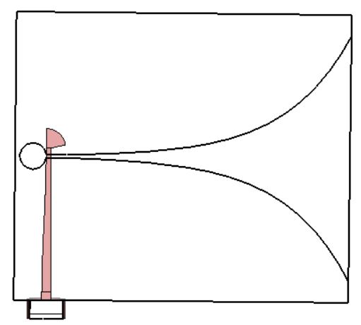
A classical Vivaldi antenna is defined by an exponentially tapered slot cut into a conducting sheet. In a printed implementation, two metallization layers on opposite sides of a dielectric form the tapered slot. The slot edge profile in the x–y plane is often described by:
\( y(x) = \pm \left( \frac{W_{\text{feed}}}{2} \, e^{a x} \right), \quad 0 \le x \le L, \)
where:
- \( W_{\text{feed}} \) is the slot width at the feed (narrow end)
- \( L \) is the antenna length
- \( a \) is the taper constant controlling how fast the slot opens
At the aperture end \( x = L \), the slot width becomes approximately
\( W_{\text{ap}} \approx W_{\text{feed}} e^{a L}. \)
Choosing \( a \) and \( L \) is essentially a trade-off between physical size and low-frequency performance: a larger aperture width supports lower frequencies and higher gain.
2.2 Approximate Frequency Scaling
For a Vivaldi antenna radiating mainly into air, the lowest useful frequency \( f_{\text{min}} \) is roughly determined by the aperture width and length relative to the free-space wavelength \( \lambda_0 \):
\( \lambda_0 = \frac{c}{f}, \quad f_{\text{min}} \approx \frac{c}{k_w W_{\text{ap}}}, \)
where \( k_w \) is an empirical factor (typically 0.5–0.7). A practical rule-of-thumb for single-element designs is:
\( W_{\text{ap}} \approx 0.5 \lambda_0(f_{\text{min}}) \;\text{to}\; 0.7 \lambda_0(f_{\text{min}}), \)
and
\( L \approx 1.0 \lambda_0(f_{\text{min}}) \;\text{to}\; 1.5 \lambda_0(f_{\text{min}}). \)
For X-band (e.g. \( f_{\text{min}} = 8 \,\text{GHz} \)), these relations give a good starting point for aperture width and total length before fine-tuning in CST or other EM solvers.
2.3 Radiation Mechanism and Directivity
The Vivaldi antenna is a leaky-wave or traveling-wave structure: fields are guided along the taper and gradually leak into free space. The aperture region behaves approximately like a flared slot with effective width \( W_{\text{ap}} \) and effective length \( L_{\text{eff}} \). The directivity can be crudely estimated using an effective aperture:
\( G \approx \eta \frac{4 \pi A_{\text{eff}}}{\lambda_0^2}, \quad A_{\text{eff}} \approx \kappa W_{\text{ap}} L_{\text{eff}}, \)
where \( \eta \) is the radiation efficiency (often 0.7–0.9) and \( \kappa \) is a taper efficiency factor (typically ~0.5–0.7). While detailed optimization is best done numerically, these formulas provide intuition on how widening the aperture or increasing the length affects gain.
3. X-Band Vivaldi Design Example
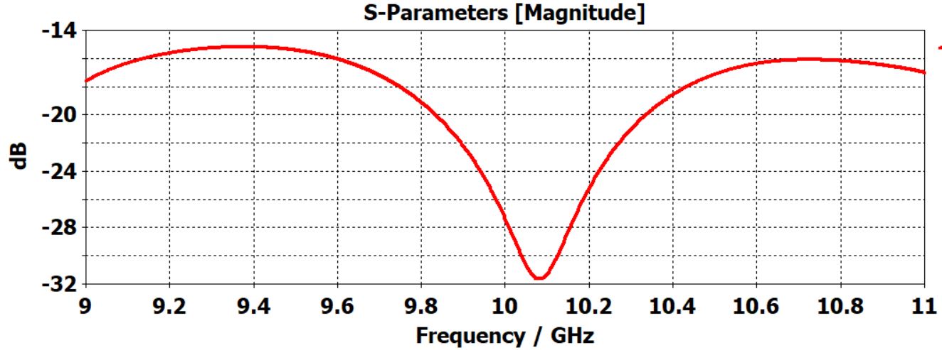
In this project, we consider a Vivaldi antenna targeting the 8–12 GHz band with good matching from 8.5–11.5 GHz and endfire radiation around 10 GHz. A typical design procedure is:
- Choose the lowest operating frequency \( f_{\text{min}} \) (e.g. 8 GHz).
- Compute the free-space wavelength \( \lambda_0(f_{\text{min}}) \).
- Set initial aperture width \( W_{\text{ap}} \approx 0.6 \lambda_0 \) and length \( L \approx 1.2 \lambda_0 \).
- Pick a practical feed gap \( W_{\text{feed}} \) (e.g. 0.5–1 mm depending on substrate and transition).
- Compute taper constant \( a = \frac{1}{L} \ln\left(\frac{W_{\text{ap}}}{W_{\text{feed}}}\right) \).
- Implement the exponential slot in CST using the parametric equation \( y(x) = \pm (W_{\text{feed}}/2) e^{a x} \).
- Design a microstrip–slotline transition (e.g. radial stub or tapered microstrip) to feed the slot.
- Optimize for \( S_{11} \), gain, and pattern stability across X-band.
4. Vivaldi Dimension Calculator (From Lowest Frequency)
Use this basic calculator to get starting values for the aperture width, total length, and taper constant from the desired lowest operating frequency. These are first-cut values suitable for initial CST modeling; you should fine-tune them based on your specific substrate, feeding structure, and performance targets.
Note: Uses simple rules-of-thumb \( W_{\text{ap}} \approx 0.6\lambda_0 \), \( L \approx 1.2\lambda_0 \) at \( f_{\text{min}} \). Treat results as starting values and refine via full-wave simulation.
5. Field Distribution and Radiation Pattern
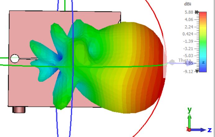
The electric field in a Vivaldi antenna is concentrated near the slotline at the feed and gradually spreads across the taper toward the aperture. At lower frequencies, radiation originates primarily near the aperture region; as frequency increases, more of the taper participates, and the effective aperture grows, typically increasing gain and narrowing the main beam.
Well-designed Vivaldi antennas for X-band show:
- \( S_{11} \) below −10 dB across most of 8–12 GHz
- Endfire radiation (main beam near 0° with respect to the antenna axis)
- Gain around 6–9 dBi for single elements
- Smooth variation of beamwidth with frequency
6. Practical Design Considerations
- Substrate choice: A low-loss microwave substrate (e.g. Rogers-series laminates) improves radiation efficiency and maintains pattern stability across band.
- Feeding network: The microstrip–slotline transition is critical; poor design here often dominates matching performance. Radial stubs and smooth flares generally improve bandwidth.
- Ground shaping: Additional shaping of ground or adding director/reflector elements can steer or narrow the beam but may reduce bandwidth.
- Fabrication tolerances: Etching inaccuracies in the exponential taper affect low-frequency performance more strongly; critical regions should be verified with accurate manufacturing.
- Arrays: Vivaldi elements are often used in linear or planar arrays; inter-element spacing and mutual coupling must be analyzed for array-level performance.
7. Downloadable Project Files (CST + Python)
The following resources are provided for academic and self-learning purposes:
- CST project of the X-band Vivaldi antenna with parametric taper.
- Python script implementing the Vivaldi dimension calculator shown above (and additional helper formulas).
- A short readme describing parameters and how to modify them for other bands.
8. References
- Gibson, P. J. (1979). “The Vivaldi Aerial,” 9th European Microwave Conference, pp. 101–105.
- Balanis, C. A. (2016). Antenna Theory: Analysis and Design, 4th ed., Wiley – Sections on traveling-wave and tapered slot antennas.
- Nguyen, C., & Menzel, W. (1986). “Broadband Tapered Slot Antennas for Microwave and Millimeter-Wave Applications,” IEEE Transactions on Antennas and Propagation.
- Pozar, D. M. (2012). Microwave Engineering, 4th ed., Wiley – Chapters on microstrip and slotline transitions.
- Prakash, S., and others – Various recent papers on X-band Vivaldi antennas (refer to latest IEEE TAP / IET MAP publications for design variants and arrays).